
In February 2014 we started work on the Longitude Prize. How we approached this project and what we learned along the way is the topic of the following posts:
In our previous Longitude Prize post we introduced challenge mapping which was our process for gaining enough understanding of the six challenge areas to start designing the challenges themselves. This post is about prototyping and testing different formulations for each challenge.
Similar to the previous research phase, we could only do this by talking to experts. This time around, we wanted them to think like competitors. We needed to understand whether the challenges we were proposing were right. Would they inspire healthy competition and novel solutions from a wide field of participants? Were they good problems?
Before we started the next round of interviews we wanted to create a proposal to stimulate discussion. So we came up with something called a challenge prototype.
The structure of a Challenge Prototype
Despite the fancy name, challenge prototypes are pretty simple, one-page documents which summarise a challenge. They state the vision of the challenge, define the problem to be solved, set the goal to be attained, detail the judging criteria and, lastly, spell out the logistics of taking part: deadlines and prize money.

All six Longitude challenge prototypes
By talking through these prototypes with experts we wanted to validate the conclusions we drew following the challenge mapping phase as well as get a better understanding of how competitors would approach such a prize. We wanted to move from the hypothetical to the concrete and get into the details.
Understanding competitors
Each interview started with the problem and goal statements in the prototype. When an expert disagreed with the proposed challenge, discussing these two statements helped us understand whether this was due to our framing of the problem, or the solutions we were expecting.
The most detailed conversations generally took place around the judging parameters and timelines. We wanted to know whether the judging criteria made sense and whether they were objective enough for solutions to be assessed against them. Equally important, we wanted to know if the challenge had a reasonable chance of being solved in the given timeframe and understand what kind of support could motivate and encourage innovators along the prize journey.
Stating the judging criteria with specific targets and limits - even if these weren’t necessarily the right ones – helped engage experts in detailed conversations around what form potential solutions might take and how they could be assessed. This allowed us to get a feel for the dynamics between the individual criteria and how they fit together.
One of the unexpected benefits of having the challenge written down were the corrections we received to our (often clumsy) use of specialist terminology. These are the types of mistakes that don’t get picked up in conversation, but stood out to experts on paper.
The last question we asked the experts we interviewed was whether they would take part in the challenge as described. If the answer was ‘yes’, then this was a positive sign that we were getting close. If the answer was ‘no’, then this was a good opportunity to ask why.
At Science Practice we’ve been having a go at DIY microfluidics using just plastic and paper:
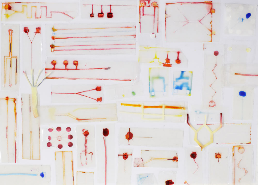
Microfluidic chips made in the Science Practice studio
Attolitre plumbing
The world’s most expensive wine costs about £12/ml, while a run-of-the-mill protein called angiogenin used in biochemical experiments costs about £120/ml. The price of biological reagents is an obvious motivation to shrink experiments to reduce volumes, and in addition, fluids on a small scale behave in interesting and useful ways. Miniaturising experiments to the point where the volumes involved are microliters (down to attolitres) gives them the title microfluidics. Tiny streams of fluid are pumped into micrometer (and smaller) channels which means that an entire experiment/reaction/process involving stages like sampling, mixing and diluting can take place on a lab-on-a-chip smaller than a stamp, automatically and very fast.
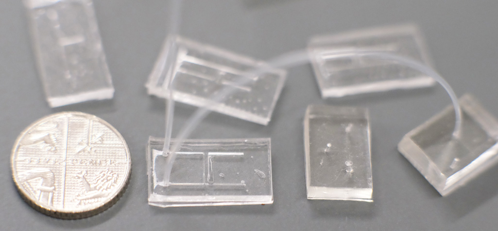
Conventional microfluidics chips made from PDMS, with H and T-junctions connected by microtubing. A five pence coin is shown for scale. Fabricated by friends in the Boutelle lab at Imperial College.
DIY microfluidics
Microfluidics are used as far afield as fuel cells and have found many uses in biological analysis, and specifically in health diagnostics. While they do reduce costs by reducing volumes, the chips themselves are still expensive to produce, requiring a laboratory. Here at Science Practice we are curious about the future of organ-on-a-chip technology, which involves culturing cells in microfluidic chips to mimic organs. Inspired by the push to bring down the cost and technical barriers of microfluidics, we decided to get our hands and our studio dirty and see how close we could get to making our own microfluidics chips in the studio.
Passive microfluidics
A variety of disease markers can be detected in biological fluids and low-tech tests could be used in remote places, in emergency situations and in the home. Paper was popularised as a microfluidics material by the Whitesides group at Harvard University, who patterned paper with hydrophobic areas to create millimetre-sized channels. A feature of microfluidics is the slow and steady laminar flow of fluid which happens in tiny channels. A similar situation occurs when absorbent paper draws in water. This natural wicking by capillary action means that pumps are not needed to transport fluids through paper channels.
Because passive microfluidics don’t require external pumps (and associated equipment like power sources), they can be small, portable, disposable, easy to distribute and operate, low-cost, technically simple to make, and they only need tiny amounts of sample fluid. Passive systems are therefore well-suited for use in the field or in parts of the world without access to advanced manufacturing and clinical technology.
In addition to paper, experimentalists in the lab and beyond have started to replace the PDMS and photolithography of traditional microfluidics with low-tech materials from Shrinky Dinks plastic (in which macro-channels are cut and shrunk down to micro-channels) to Sharpie pens which create a water barrier. We considered a variety of easily available materials for passive microfluidics and decided to start with the following three combinations: Wax-Paper, Paper-Tape, and Plastic-Tape.
Although the pictures which follow may look quite gory, the red fluid is not blood but food colouring diluted 1:1 with tap water (there’s a full list of materials at the end of this post). Since we have no prior experience with microfluidics, and no laboratory or specialist tools, any techniques we have come up with are assured to be low-tech.
Testing microfluidics techniques
Method 1: Wax-paper microfluidics
I was enticed by the child-like simplicity of drawing with a wax crayon on paper, which I came across in a paper by Lu et al. The principle is that wax lines on paper make a hydrophobic barrier to aqueous fluid. For extra absorbent paper which would wick liquid as far as possible I used 55% cellulose paper which is actually an absorbent laboratory wipe.
I melted the wax lines into the paper by microwaving it on a plate for 2 minutes (I also tried a conventional oven). Overall I didn’t find the Wax-Paper technique very useful in the DIY context because it’s difficult to make thin wax lines by hand, and the thinner they are the more likely they are to “leak” and allow fluid to pass through the wax barrier.
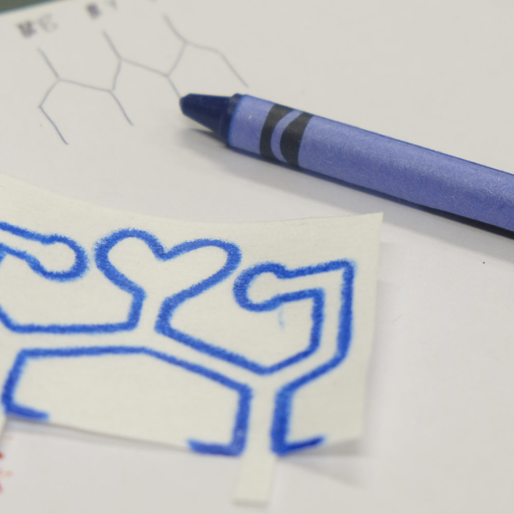
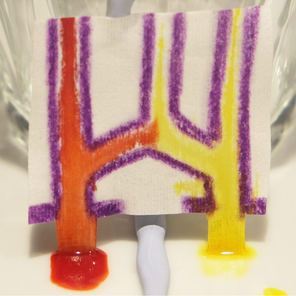
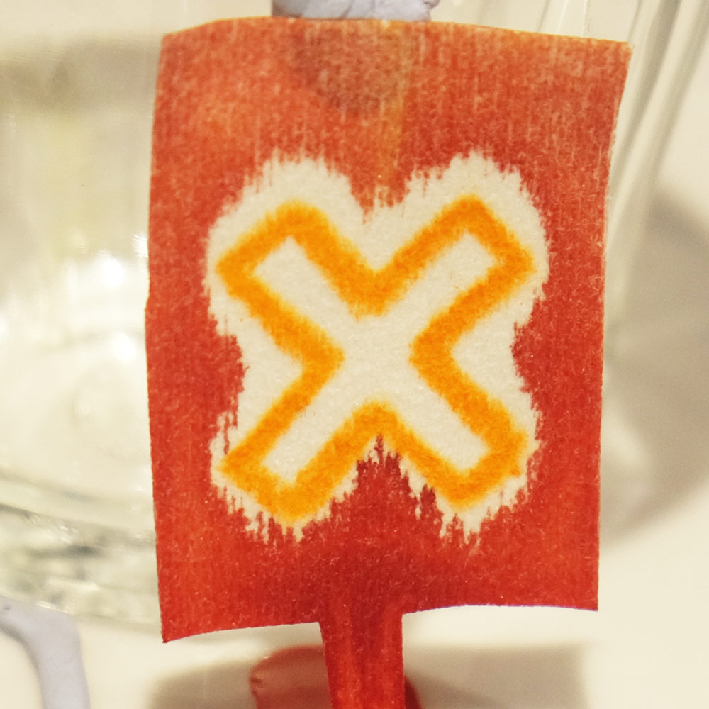
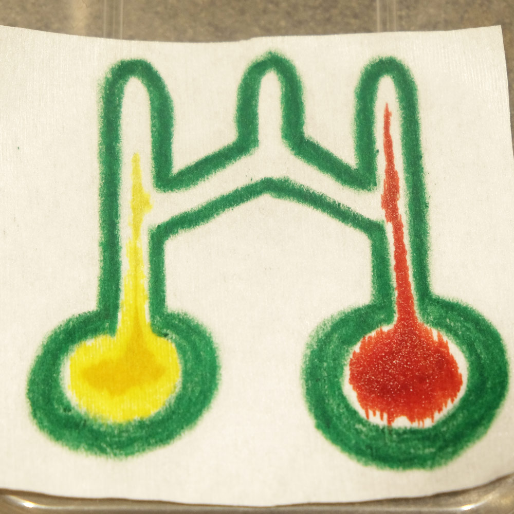
Trying the Wax-paper technique to create microfluidics. Wax lines are best at keeping fluid outside or inside of a closed path, as shown in the bottom row.
Here are some observations which I would keep in mind if developing this method further:
- Even with the sharpest crayons you need to press hard to make thick lines to contain the fluid.
- The wax line expands when heated and there is a transparent water repellent area on either side of the line.
- Wax-Paper microfluidics have a limited fluid capacity. After the channels become saturated fluid starts to overcome the wax barriers and leak out.
- Fluid takes a sneaky path along the thin side of the paper which is hard to cover in wax.
- It’s therefore easier to keep fluid outside of a closed shape or inside a closed shape.
Method 2: Paper-tape microfluidics
The Whitesides group has shown that by stacking layers of paper and tape, a multi-level structure is possible, and with a hole between levels the fluid can “jump” from one level to another, enabling 3D flow. This kind of 3D structure allows for more complicated designs which would not be possible in a single layer.
Since we don’t have the resources to hydrophobically pattern paper in our studio, I used a craft knife to cut paper into the thinnest strips possible to create channels, which ended up being about 1.5 mm wide. To create more interesting microfluidic shapes I layered the paper strips between pieces of tape and was able to get 3D fluid flow. This modification of Whitesides’ method doesn’t require (i) patterning hydrophobic areas onto the paper using photolithography which requires chemicals and UV light or (ii) cellulose paste to fill the gaps between horizontal paper layers where fluid needs to move vertically.
The following are pictures of one of our Paper-tape microfluidics devices with 3D movement of fluid. There are two planes of paper strips separated by a middle layer of double sided tape which has tiny holes in it to let fluid pass from one plane to another. The device is sealed on either side by regular clear tape. In the left image the dashed red circles highlight inter-layer holes which allow 3D motion of fluid:
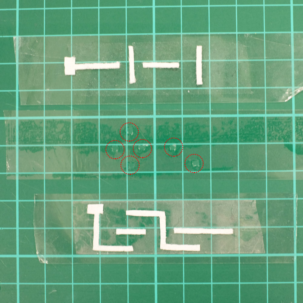
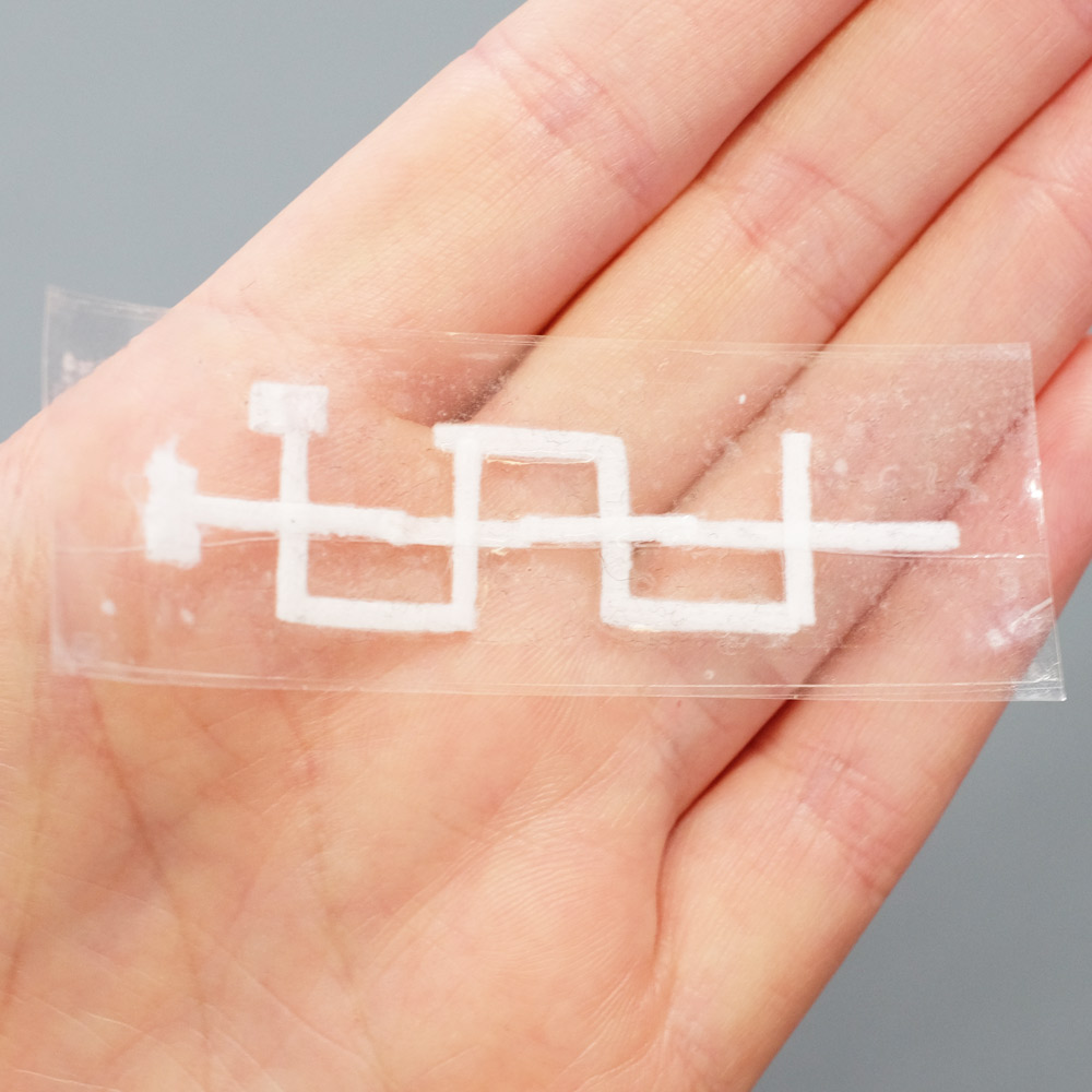
A 3D Paper-tape microfluidics chip. Left: the three layers of the device before assembly, with dashed red circles highlighting holes that allow inter-layer flow. Right: the finished chip.
Next is a photo which demonstrates the Paper-tape device’s 3D flow. The thick squares are sample inlets where a drop of fluid is placed. The red fluid weaves under and then over the blue fluid twice. If this chip was 2D then the red and blue would mix, but in this case the streams remain independent:
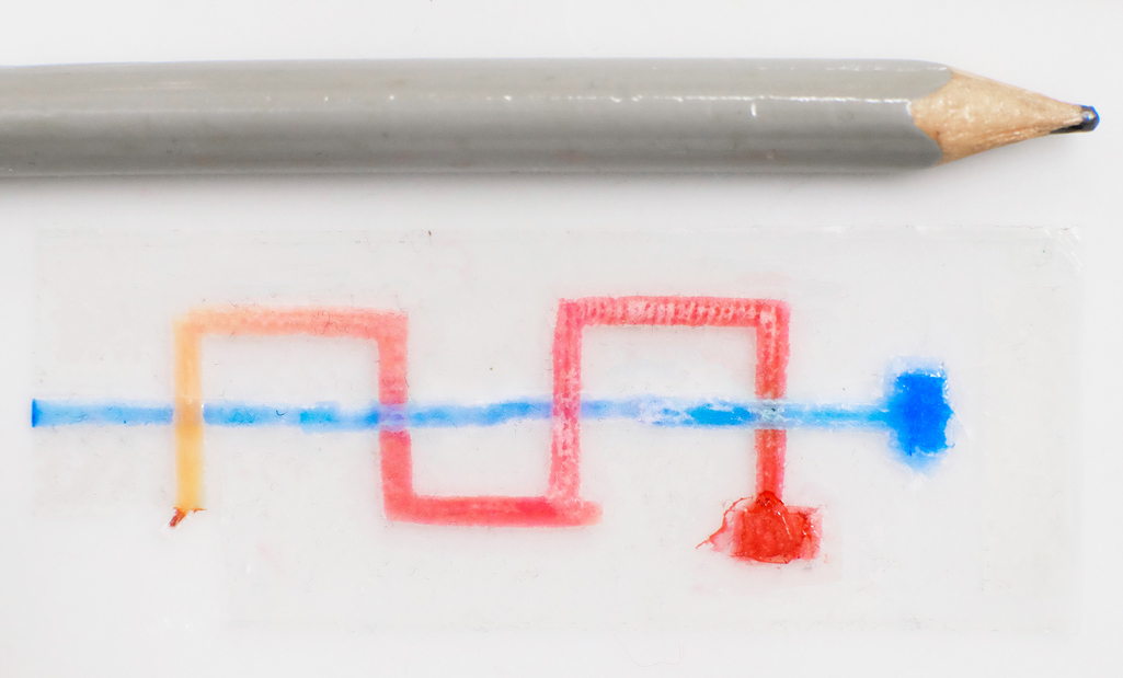
A Paper-tape microfluidic device demonstrating 3D flow. The red fluid weaves under and then over the blue fluid twice, without mixing.
This device has only two layers, but I was able to create a device with fluid moving to four different layers (I didn’t try anything more complex but I think it is entirely possible). I found that vertical flow in both the direction of gravity and against it were possible. The most difficult part of creating these kinds of devices is lining up the strips of paper and the holes.
Pumps not only propel liquid around, but they can also control the speed of flow. With paper microfluidics we can use different papers to create different wicking speeds, for example fluid moves more slowly in coffee filter paper than absorbent laboratory wipes. Another possibility for controlling flow is cutting the paper strips at different angles in the paper. The fastest wicking which is 0.8 mm/s happens when the fluid moves parallel to the grain of the paper, and the slowest which is 0.3 mm/s happens when the fluid moves perpendicular to the grain. Theoretically any speed between these two extremes is possible by cutting at different angles. The following video shows fluid moving through different paper angles as it branches out in a tree-shape cut from a single sheet of paper. The central branch is cut parallel to the paper and is therefore the fastest.
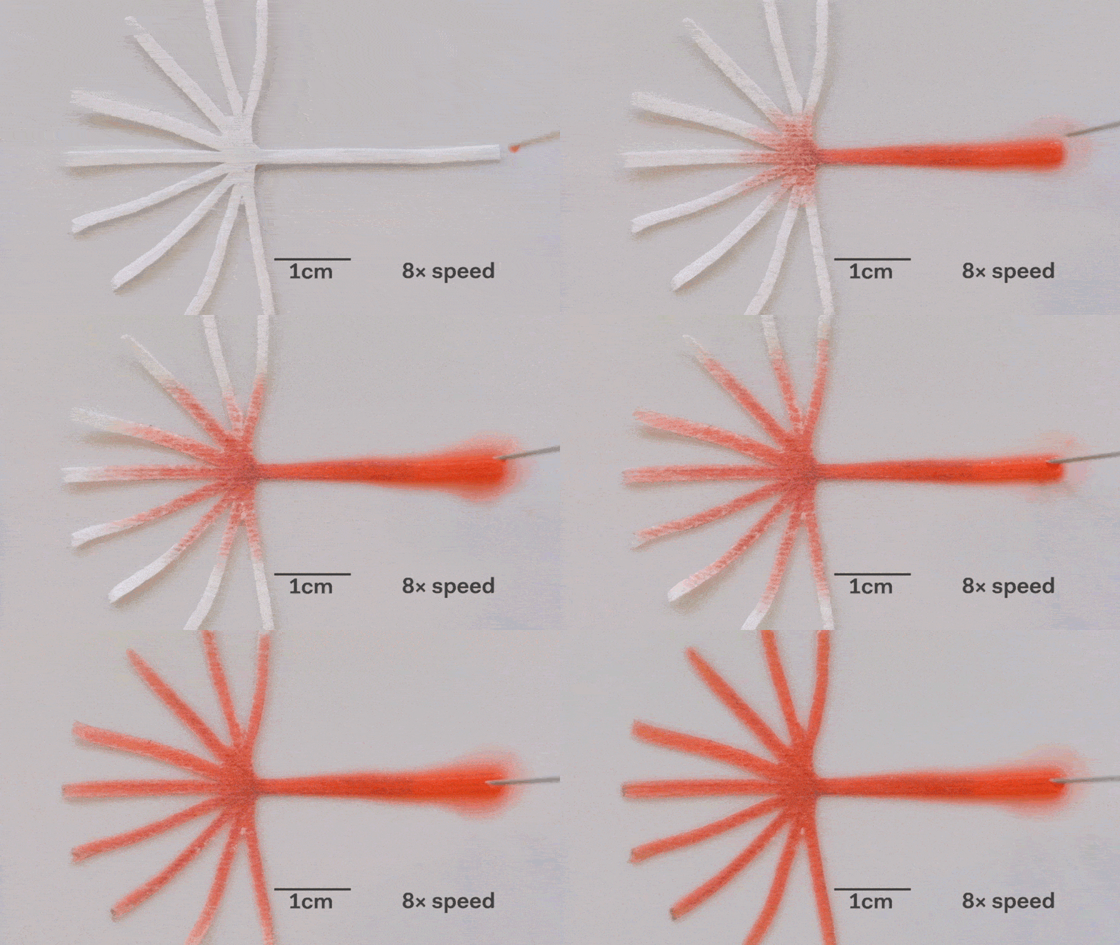
The speed of fluid flow in paper microfluidic channels can be controlled by cutting paper at different angles to the paper grain. Here the central branch has the fastest flow as it is cut parallel to the grain. This animation is sped up 8 times.
Here is a close-up of the paper tree showing that the fluid moving parallel to the paper grain (central branch) is the fastest. In the same time the fluid in the branch with perpenduclar grain has moved only about half as far:
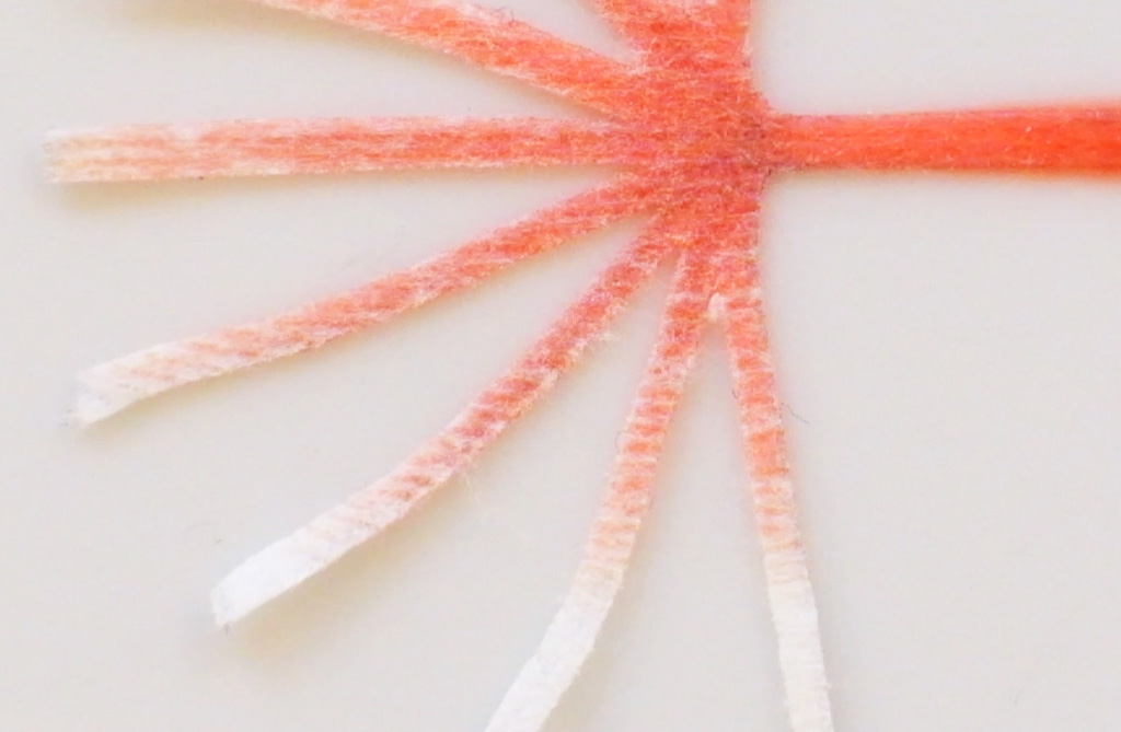
The speed of fluid flow in paper microfluidic channels can be controlled by cutting paper at different angles to the paper grain. Fluid in the the central branch cut parallel to the grain has reached the end, while in the vertical branches cut perpendicular to the grain it has not yet.
Method 3: Plastic-tape microfluidics
This method involves stacking layers of double-sided plastic tape and plastic strips cut from transparency/overhead-projector sheets (sometimes called Mylar sheets). I started by cutting channels about 1.5 mm wide in double sided tape, and sandwiched the tape between two layers of plastic. This creates a channel in the middle layer. The following image shows fluid being drawn up into the channel and then forking into 3 branches:
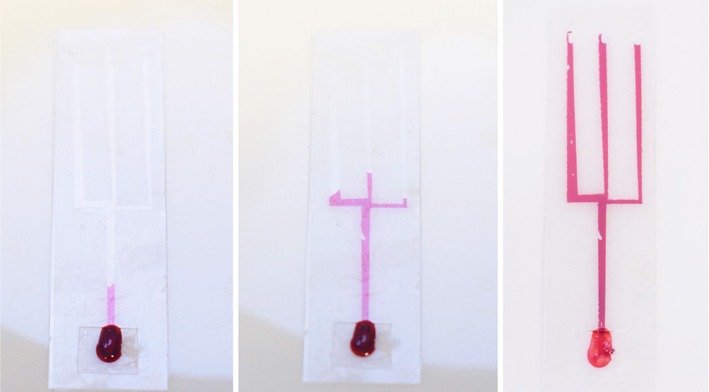
Microfluidic chips made in the Science Practice studio using the Plastic-tape method with thick channels.
A simplification of this method arose when I observed that I didn’t need to cut a 1.5 mm channel because fluid is drawn by capillary action along any edge. I realised that I could make a channel by merely make a single cut in some plastic sheet and sealing this cut with tape on both sides. Lighter scratches in the plastic also work although it’s hard to maintain a consistent depth when scoring by hand, so it’s easiest to cut all the way through. The following video shows fluid flow in one of these extra thin channels in real time. At its fastest it has a speed of about 1.4 mm/s:
A Plastic-tape chip with thin channels, demonstrating the speed of fluid flow.
The channel needs to be open at the end for capillary action to move fluid along. If it’s not then capillary action needs to work against a pressure build-up in the channel. This means that fluid flow is in one direction only: towards the opening. When designing chips you therefore have to keep in mind that fluids must have an unhindered path to the channel opening. When several streams converge all but one will stop flowing, and this makes mixing streams tricky but not impossible (more on that in another post.)
This open-end requirement can also be used to make a valve that starts and stops flow. Flow can be turned “on” when the channel is open at the end and turned “off” when the end is closed. I thought it would be useful to be able to load multiple inlet pads and only trigger the start of flow on command. I created chips with blind-ended channels which can be loaded with droplets, and fluid only flows when the ends are cut off to open them up:
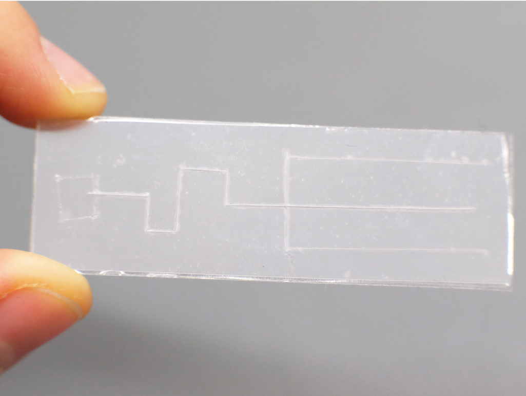
A Plastic-tape chip with thin channels and branches, sealed off at the end.
The following video shows that fluid only enters the channel when the end of the chip is cut off with scissors. After this point the video is sped up 70 times to show the path of the fluid (which is slower than the previous video because of its tortuous path):
A Plastic-tape chip with thin channels. Fluid is loaded onto the chip, and cutting off the end of the chip triggers fluid flow driven by capillary action. After this point the video is sped up 70 times to show its path.
It is possible to get 3D flow across both the thick the thinly scored channels, but I’ll also save that for a future post.
A useful function that these types of microfluidics can perform is distributing a sample to multiple points so that different analytes can be quickly tested at each point. For example a drop of blood could be tested for glucose, proteins and pH. Blood could be dropped into the middle of a device like this, and the blood would quickly be distributed to multiple pads for testing.
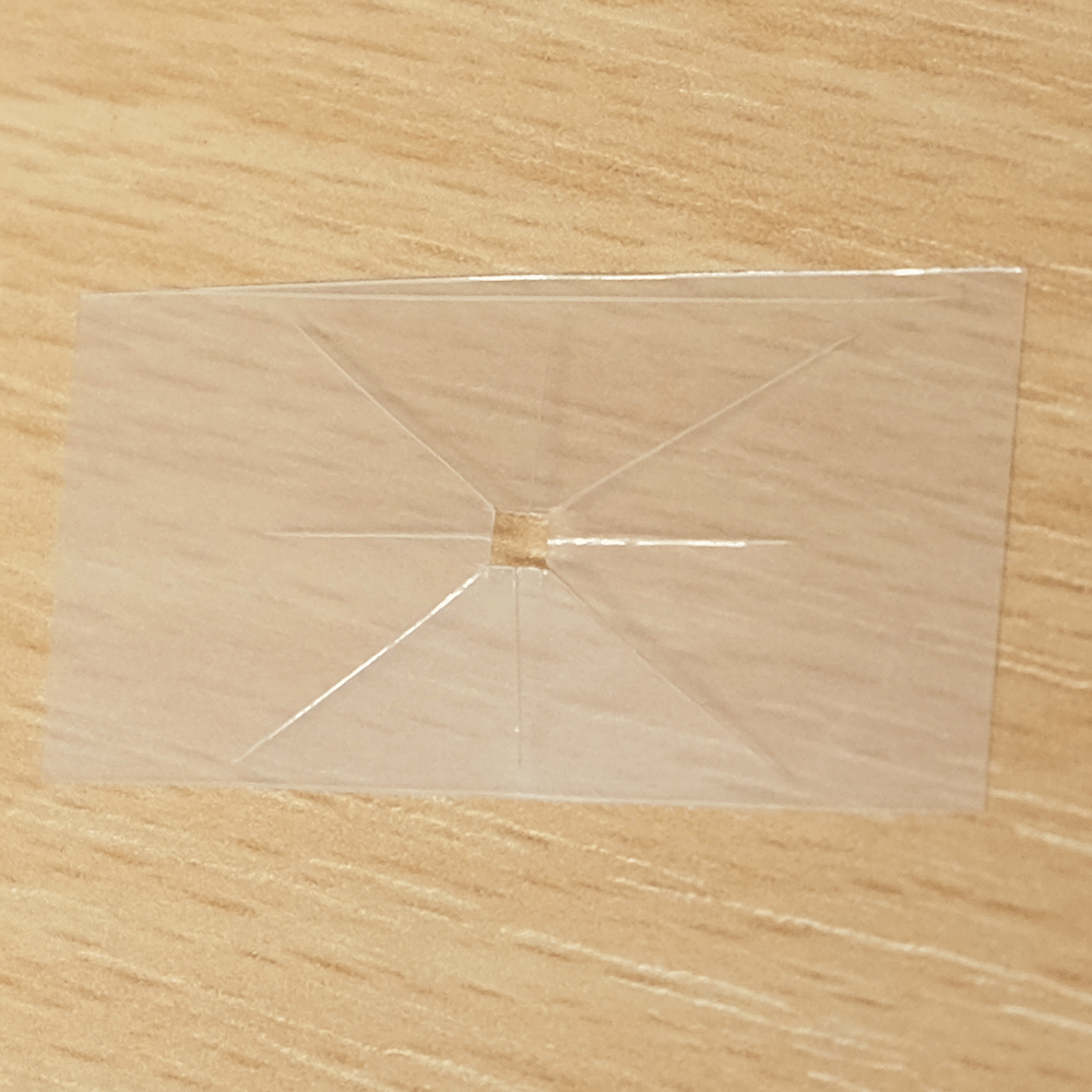
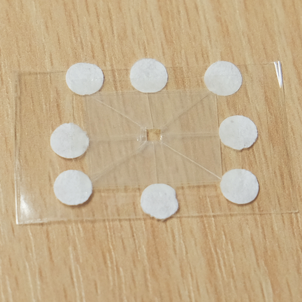
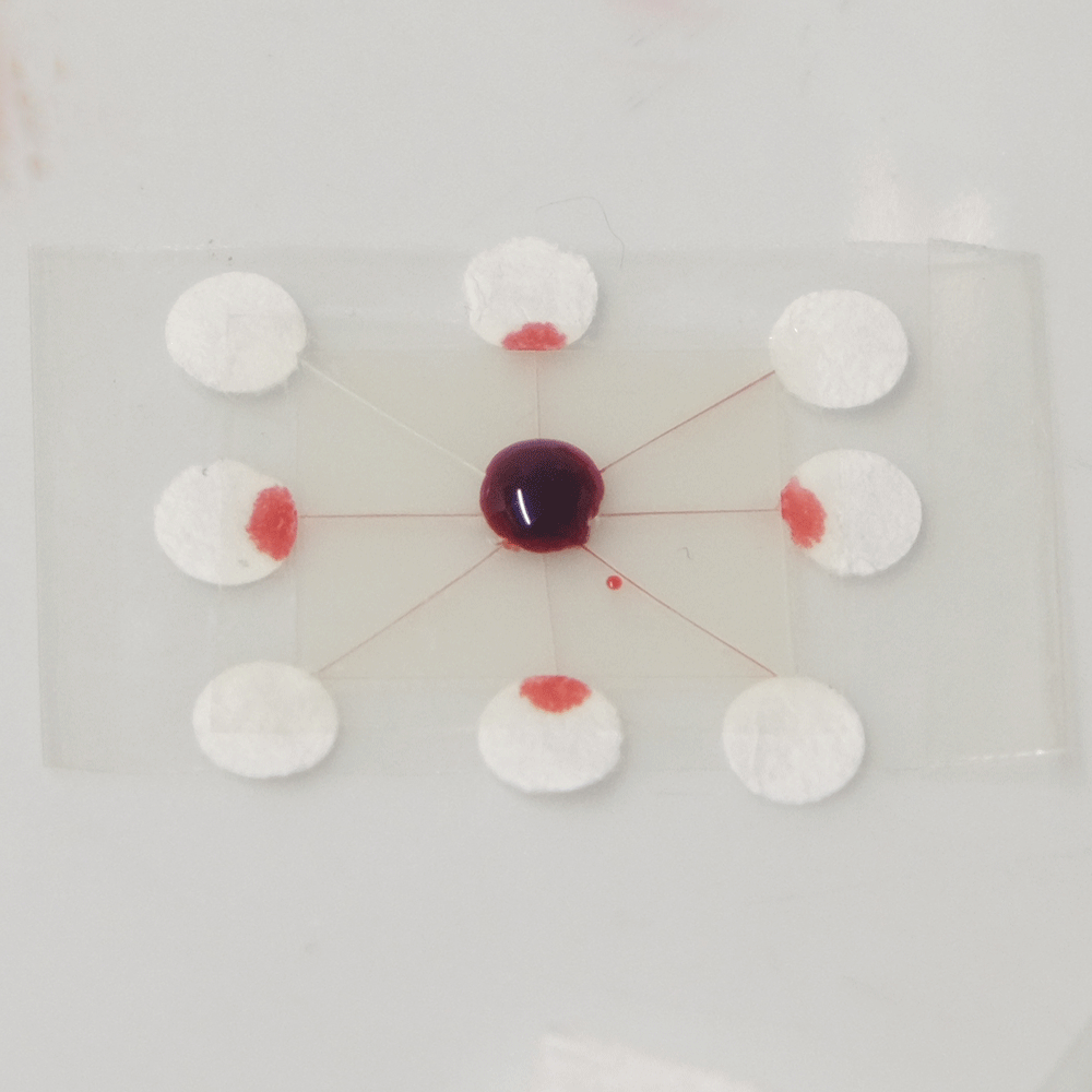
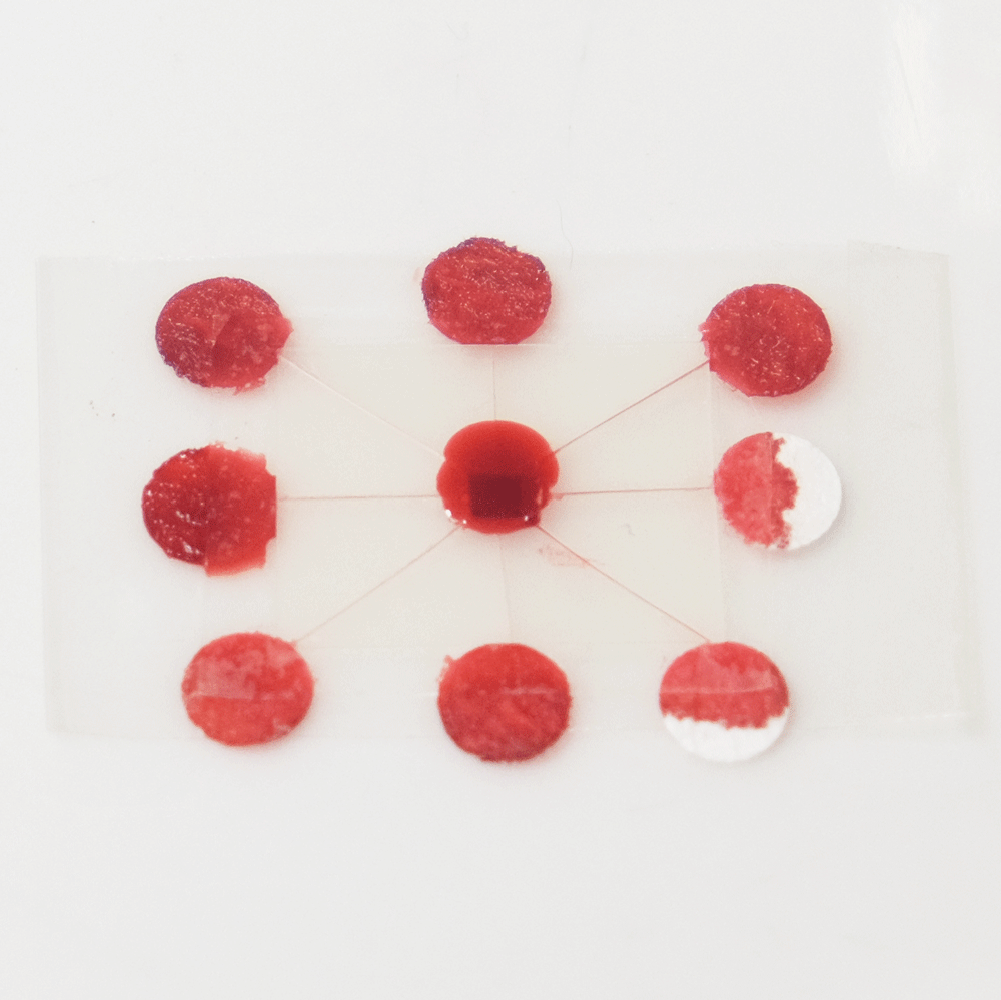
A sample distributing chip. The top row shows construction and the bottom row shows operation of the device. A sample of biological fluid could be placed in the centre of the Plastic-tape chip. It is distributed to multiple points where it could undergo different chemical tests quickly.
I created this sample distributor by scoring channels in transparency plastic and sandwiching this in clear tape on either side. (Maker note: score the plastic almost to the end of the chip, attach sticky tape and then snip off the edges so that it doesn’t fall into eight pieces.) At the end of each channel is a paper pad to draw the sample out of the chip so that a user can add reagents, or have pads that are pre-loaded with reagents. Perhaps a colour change could be observed, or the pads could be removed for further analysis. The paper pads were made by using a punch on coffee filter paper, as super-absorbent cellulose paper was too fibrous to punch.
Verdict
The Wax-paper method was a fun way to get started and get used to working with the paper and fluids, however when made by hand the channels end up being very large.
The Paper-tape method is excellent for fluid travelling over short distances. It has the advantage of allowing multiple channels to converge into one and so mixing is possible. This opens up the possibility of making many useful devices like H-filters and T-sensors as demonstrated in Paul Yager’s work at Washington University.
Of the three methods, I think Plastic-tape with very thinly scored channels has the most potential. The channels are very quick and easy to cut and they use a really tiny sample volume because the channels are so narrow.
However I think it would be great to combine paper and plastic channels in a layered 3D device to get the most of both methods: intricate plastic channels with the mixing capability of paper, and thicker plastic channels for varying speed. Watch this space!
Shopping list
Here’s a list of the materials I used in these experiments:
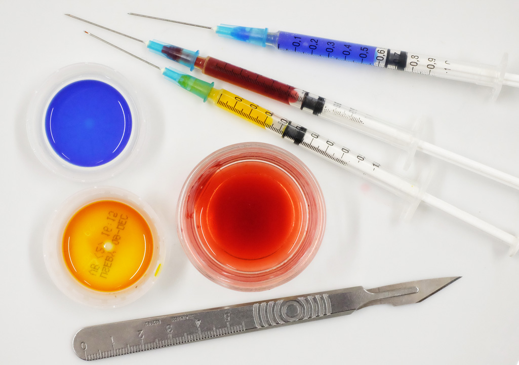
We used food colour as a visible fluid.
- Essential Waitrose natural food colour (red was my favourite because it was the most mobile across all materials)
- Mylar stencil/transparency sheets, 125 micron thick
- 3M Scotch Permanent Double-Sided Tape
- Absorbent laboratory wipes: W50 Polyester Cellulose Wipes by Integrity Cleanroom
This is Part 3 of our report from the Communicating Across the Cosmos workshop on interstellar message composition held at the SETI Institute in Mountain View, California, November 10–11th, 2014. You can read Part 1 here and Part 2 here.
In my previous posts I introduced the context of historical and modern activities centred around communication with extraterrestrial intelligence (CETI). I also outlined some of the most interesting problems discussed in the field of CETI today.
In this post I will focus on my own research into the limits of communication in CETI. It is based primarily on the Lingua Extraterrestris dissertation I wrote for my masters degree at Central Saint Martins College of Art and Design in 2011, but since then I have taken the research with me to several events and venues, and discussed it on the wider CETI forum.
Our human endeavour to communicate with another mind starts on Earth. According to various estimates, there are between 5,000 and 7,000 languages spoken on our planet. This multitude and variety of languages has always been a great challenge for humankind, but it has also inspired people to find ways of bridging this gap in communication. In 1887 a Polish-Jewish ophthalmologist, Ludwik Zamenhof, published Esperanto — a constructed language designed to help local Polish-, Yiddish-, Lithuanian-, Belarusian-, Russian- and German-speaking communities in his city of Białystok to communicate.

The Tower of Babel by Pieter Bruegel the Elder, Kunsthistorisches Museum, Vienna
Since the end of 19th Century our understanding of communication has evolved and expanded. For me personally — that is from the perspective of a communication designer — the most interesting question that remains to be answered is about the limits of communication. In Lingua Extraterrestris, as an effort to find out more about these limits, I investigate historical and fictional examples of CETI. On the historical side, I look into the documented acts of sending interstellar messages (Pioneer plaque, Voyager record, Arecibo message) and receiving alleged extraterrestrial signals (Little Green Men 1 or the Wow! Signal), as well as into the development of artificial mathematical languages for CETI use (Lincos). On the fictional side, I analyse stories of encounters with alien civilisations from science-fiction novels by Stanisław Lem (Solaris, His Master’s Voice and Fiasco), from science-fiction films by Steven Spielberg (Close Encounters of the Third Kind) and Paul Verhoeven (Starship Troopers), and from reports on extraterrestrial activity on Earth (first UFO sightings by George Adamski and accounts from independent thinkers documented by Sir Patrick Moore).
In search for a framework that would support and guide the analysis of historical and fictional examples of CETI, I refer to two well established general models of communication. The Roman Jakobson model is used to analyse spoken communication. Among six parameters that Jakobson identifies to characterise any possible human conversations, there are three that apply very well to CETI: contact, context and code.

Roman Jakobson general model of communication
The second model is the Shannon-Weaver model of communication which has been dubbed ‘the mother of all models’, because it characterises the process of signal transmission in a very universal way. In his model, Claude Shannon included one parameter without which discussing CETI would not be possible: channel. These four parameters sourced from two prevalent models of communication — channel, contact, context and code — serve as useful lenses, through which I explore CETI examples in Lingua Extraterrestris.

Shannon-Weaver general model of communication
Channel
Shannon defines channel as ‘merely the medium used to transmit the signal from transmitter to receiver.’ There are many examples of the channel. It can be the 1420 Megahertz radio frequency selected for project Ozma. It can be the physical shape of the metal Pioneer plaque. It can also be the vibration of air carrying sounds from vocal cords to ears.

In his novel Solaris Stanisław Lem tells the story of the impossibility of finding a single channel for communication. The plot follows human scientist based on planet Solaris. Solaris is entirely covered by the Ocean — a single, planet-sized organism which is sentient and intelligent. Human scientists make numerous attempts to communicate with Solaris using a range of channels: visual observation, nuclear explosions, X-rays. Everything fails. No communication can be established. At the same time the Ocean exercises its own channel which is completely unfamiliar to human scientists. It is some kind of a mental channel through which the Ocean probes human minds and accesses their deepest memories. Later, those memories are manifested in the form of Visitors — projections of people with whom scientists had tragic personal relationships. None of the channels used by scientists or the Ocean facilitates communication. Instead, we see a sequence of actions and reactions, experiment and failures, with each party being probed by another through various physical or mental media. The Ocean is so dramatically different from humans, that any communication, any meaningful exchange of signals, finding a single common channel for sensible interaction is beyond our reach. Finding one common channel to establish communication is impossible on Solaris.

Solaris — stills from the film by Andrei Tarkovsky (1972) based on the novel by Stanisław Lem
Contact
Once a channel for communication can be found, contact can be established. Jakobson defines contact as a function of language used ‘to establish, to prolong, or to discontinue communication’. When the phone rings, it tells us that there is someone on the other end of the line. We pick up, because we know that they have something to tell us. Any signal emission can become transmission, once we get a confirmation that someone is receiving it.

Contact is a key phase in the communication process when both parties share the awareness of being connected. In Close Encounters of the Third Kind Steven Spielberg tells the story of an extra terrestrial intelligence (ETI) making contact with humanity in a progression of steps and through a range of channels. First the ETIs announce themselves to terrestrial authorities by returning lost equipment and leaving it in impossible locations. They return a missing squadron of World War II bombers and leave SS Cotopaxi in the middle of the Gobi Desert. These strange events alert the scientific community. The contact is aimed at winning their attention. ETIs also contact a number of individuals. Roy and Jillian both witness a UFO which exposes them to very bright, burning light. That light impregnates them with a mental image of a shape. Soon they start seeing that familiar shape in everyday objects. They become obsessive about it and try to find out what it means. Later, we learn that the shape is personalised invitation to a rendezvous with the ETIs. The ETIs also address whole communities. Pilgrims in Dharamsala, India receive a 5-tone musical phrase played by a UFO. In this way ETI probes the channel to see if there is someone to on the other end. There is. The 5-tone phrase is broadcast back into space and in response ETIs send a signal containing 6 digits. These are coordinates of a rendezvous place. Throughout the film we follow this elaborate and well curated plan to win attention, establish contact and to set up a rendezvous place near the Devil’s Tower in Wyoming where the grand finale takes place.

Different ways of making contact — stills from Close Encounters of the Third Kind (1977) by Steven Spielberg
Context
Context is not as clear-cut as other lenses. In the context of CETI it can be defined as: the ability to relate to the other mind, to understand the reasons and standpoint from which they communicate. Imagine we tell an ETI that, due to the length of time between us sending a message and them responding to it, their messages will be received not by us but by our descendants. In this communication, we would have made the assumption that, like us, the ETIs are also mortal and have a shared contextual understanding of life, death and reproduction. But what if the ETIs are eternal or immortal? They will not understand the concept death or passing of generations. Referring to our descendants will simply make no sense to them unless, of course, that they understand our context…

In science-fiction aliens are often depicted with a strong terrestrial bias. Their context is made similar to ours, which helps both races to communicate. That’s why Klaatu in The Day The Earth Stood Still appears as an English gentleman. In Starship Troopers directed by Paul Verhoeven and based on Robert A. Heinlein’s novel, aliens also look somehow familiar. But this does not help our communication. We see a story of an interplanetary war between two species: Humans and the Bugs. In CETI discourse, context can be linked with the problem of the environment, in which life forms emerge and evolve, adapting to specific conditions. In Starship Troopers we see Bugs shaped by the same environment in which we have evolved: medium-sized rocky planets, same gravitational forces, same air to breathe, same meat to eat. Even our anatomy and physiology are similar. But there is even more… Both species are curious to learn about another race. However, they only do this to find and exploit another’s weakness in the military conflict. Both societies are brutal, militant and with a strong hierarchical organisation. Many shots show superficially chaotic, swarm-like behaviour of human and bug soldiers. Finally, they both exhibit a strong need to expand and colonise other planets. Humans and bugs share a similar environment and context. In other science-fiction stories this would normally help civilisations to communicate. But here they also share the same goal: to exterminate and colonise the other. In Starship Troopers sharing of the context is the underlying reason for a brutal, escalating conflict.

Humans and Bugs in Starship Troopers — stills from the film directed by Paul Verhoeven
Code
Code it the final lens that we use to inspect CETI. It relates to the compatibility of languages. If code is shared, signals can be decoded and read on both sides of the wire. In our daily experience codes are languages used in different countries of the world. The Morse code is an artificial code invented for the purposes of early telecommunications. Codes can also be more subtle and deeply ingrained in human cultures. In the CETI debate, the argument is that we should either send a message with a key, or use codes based on universal systems, such as basic mathematics. However, science-fiction knows other codes…

In Stanisław Lem’s His Master’s Voice we read a story of decoding of a cosmic message intercepted from space. The novel is a personal memoir of a mathematician, professor Hogarth, who describes four types of codes:
-
Type I consists of all languages. These are systems of signs and meaning used by humans to communicate between themselves using, for example, German, sign language, traffic signs;
-
Type II includes all systems of modelling signals (for example television signal or grooves in CD-ROM discs and vinyl records);
-
Type III comprises all protocols for production or execution used in machines to script and control automated operation;
-
Type IV consists of any codes that are not made by human. These are a-cultural codes, description of things. In these codes organisms talks to organisms. They refer to physical, universal, detectable and constant phenomena (e.g. the genetic code).
There are no clear-cut distinctions between these four types. For example an ovum is both a production protocol, as well as a description of itself and of the organism it will grow into. The interstellar message in His Master’s Voice turns out to be an a-cultural code. Something between type III and IV. A combination of a production protocol and an ‘a-cultural’ description of a thing. In his memoir, Hogarth concludes that for humans it is impossible to create a-cultural codes, because we are defined by our cultures. All codes created by humans must contain traces of culture. And this cultural contamination can never be reduced to zero.

Channel, Contact, Context and Code — these four lenses are useful in guiding our analysis of CETI examples in science fiction, but they can be even more valuable when applied to the very starting point of CETI as a scientific endeavour — to the Drake Equation. As Douglas Vakoch observed in his opening remarks for the ‘Communicating Across the Cosmos’ workshop at the SETI Institute, the earlier terms of the Equation are already well explored, while the later ones still require a lot of exploration. To better understand what the fc term involves, I suggest considering it as a composite of four sub-terms discussed above: Channel, Contact, Context and Code.

I discuss this expansion on fc in more detail in my dissertation, Lingua Extraterrestris. The full text is available here.

In February 2014 we started work on the Longitude Prize. How we approached this project and what we learned along the way is the topic of the following posts:
Antibiotics, Dementia, Flight, Food, Paralysis, and Water. Our first task on the Longitude project was to map out the main barriers to innovation within each of these areas and understand what are some of the most promising routes towards a solution. Given the short timeframes of the project, how could we best engage with the expert community to build this understanding?
At Science Practice, we take a design-led approach to research. Plainly put, rather than asking experts to tell us their opinion on a topic, we present them with a specific proposal and seek their response to it. We often refer to this proposal as ‘research stimulus’. For this first phase of the Longitude project the research stimulus took the form of a map.
As with a map of a physical landscape, ‘challenge maps’ - as we started calling them, described the barriers to be overcome or circumnavigated, promising pathways to a goal, and the milestones along the way. The maps aimed to translate the scientific, technical, and social factors surrounding a challenge area into an imagined landscape.
Before we started work on Longitude 2014, we decided to see if we could make a map for the original Longitude Act of 1714:

We put together this map to illustrate some of the potential solutions to the Longitude problem from the perspective of a natural philosopher in 1714. Elements of the map have been sourced from the fascinating collection of Papers of the Board of Longitude archived at the University of Cambridge.
The main aim of challenge maps wasn’t to achieve accuracy, but to become a starting point for conversations with experts. We wanted them to be engaged in the research process, explore alternative solutions, and play an active role in shaping the landscape defining each challenge area.
Challenge Maps in Practice
One of the first things we learned was that representing a challenge topic as a two dimensional map didn’t always work. Some topics were simply too complex, especially when cultural and political factors needed to be represented. The Food and Dementia topics were certainly the most difficult. For the Water, Flight, Paralysis, and Food challenge topics, however, the approach seemed quite natural.
Successive iterations of the challenge map for the Water prize
Used as research stimulus in interviews with experts, the maps triggered different responses. While some experts found them very helpful and used them to build their arguments, others criticised or simply ignored them. We tried to make sense of each of these reactions to further develop our understanding of the six challenge areas.
Successive iterations of the challenge map for the Paralysis prize
As well as helping us develop our factual understanding of the challenge topics, we would often receive some surprisingly nuanced feedback. In early drafts for the Antibiotics challenge map we represented the history of infection control as a war between two opposing armies: microbes and humanity. This war metaphor appears regularly in the literature and popular press so it seemed sensible to appropriate it for our challenge.

First version of the challenge map for the Antibiotics prize
However, when presenting this map to experts they reacted strongly against it, arguing (rightly) that the war metaphor plays a role in shaping people’s attitudes towards bacterial infections and helps to propagate the irresponsible use of antibiotics.

Final version of the challenge map for the Antibiotics prize
Maps allowed us to set a frame around the challenge area without actually imposing any direct constraints on what could be included. Elements of the map, such as the relative position of objects or landmark features such as bridges or rivers, became signifiers for barriers or opportunities for innovation in the challenge area. By encouraging interviewees to edit the maps we not only received information about potential fields or technologies which could generate solutions, but also contextual information about the likelihood of their success or ability to be attained within the lifetime of the Longitude Prize.

An annotated challenge map for the Paralysis prize following an interview with an expert in the field
Synthesising Expertise
Seven weeks and 60 interviews later, we ended up with six very different challenge maps. While some developed along the initially defined structures, others were redrawn into completely different shapes as our understanding of the challenge areas changed. Some maps were quite clear and concise, others were still rather abstract or cluttered - making plain the issues in need of further research.

All six Longitude challenge maps
Although the maps themselves evolved through this process, they are actually more of a byproduct. As research stimulus, they enabled us to have guided yet flexible conversations with experts, encourage them to explore novel technologies, and suggest potential pathways to solutions.
The next step for us was to build on these conversations and start shaping the basic structure of the six challenge prizes. This became the challenge prototyping phase of the Longitude project, which we will discuss in our next post.

In February 2014 we started work on the Longitude Prize. How we approached this project and what we learned along the way is the topic of the following posts:
A challenge prize is a very simple idea. A problem is identified and publicised along with the offer of a reward to the person or organisation who can find the first or best solution. Identifying the problem, however, is a challenge in itself.
A challenge fit for a prize
When we started working on the Longitude Prize in early 2014, the term ‘challenge prize’ was unfamiliar to us. Yet we resonated to the underlying concept – engaging with experts to design competitions that could advance scientific inquiry and, hopefully, the discovery of solutions to some of the world’s most pressing problems.
One of the first things we learned while working on Longitude was that not all problems can be made into good challenges. The problem identified for a challenge prize needs to be:
1. Simple to understand and articulate
- It is very difficult to publicise a challenge that is too complex to be described succinctly and clearly.
2. It has to be a real problem, not a manufactured one
- It is very easy to be drawn to what look like real problems, only to find that they are in fact artificial problems based on too many assumptions.
- This becomes especially treacherous when researching problems faced by people in other geographies and cultures.
3. There need to be people interested in solving it
- A good challenge prize will galvanise a community of people who have been thinking about the problem for a while.
- A challenge prize is open to everyone, but if no-one sees themselves as the right person to solve it, setting a challenge will have little benefit.
4. It has to be soluble
- The challenge must not require a change to the basic laws of physics in order to solve it (we fell foul of this a few times).
- This consideration is especially relevant for prizes that aim to encourage innovation in mature fields of engineering like aviation and water processing, where the temptation might be, for example, to demand impossible reductions in energy usage.
- A problem might be too culturally or politically complex to be able to benefit from a technological solution.
5. It can’t have been solved already
- You don’t want to open up a Challenge Prize only to find that it has already been solved by a team of researchers you weren’t aware of.
We were given six broad challenge areas: Antibiotics, Dementia, Flight, Food, Paralysis, and Water. As our involvement in the project grew, our task became that of crafting good challenge prizes out of these areas.
Valuing expertise
We are not experts in any of these fields but we were lucky enough to work with expertise sourced from an international group of advisors. What we needed was an understanding of the key challenges within these areas, the likely areas of opportunity, and the motivations of potential participants in the challenge.
The Longitude Prize Journey
Our work on the Longitude Prize 2014 ended up being divided into three stages: challenge mapping, challenge prototyping, and challenge reporting. In the upcoming Longitude posts we will explain these phases individually to illustrate some of the materials used, their application in practice, and their outcomes.


